Thermal cycling controller for desktop PCR machine
November 2019
In this project I helped a HAX startup working on a desktop PCR machine targeted at pre-screening blood samples in large hospitals. I designed the controller for the Peltier device (or TEC) they used to induce PCR in a microfluidic chip.
Step 1: understanding PCR thermal cycling
PCR is a biochemical process used to generate millions of copies of a single DNA molecule in a short time. The process has 3 main steps that need to be repeated between 20-30 times:
Denaturation (94-98 deg C) separates the two strands that make up a template DNA molecule
Annealing (55 to 72 deg C): primer molecules bind to target regions on each DNA strand
Extension (68 and 72 deg C): DNA polymerase extends the end of each primer along the template DNA strand.
To implement this thermal cycling process in the startup’s machine, we used a Peltier device with an NTC resistor as temperature sensor on the interface between the heated side of the Peltier plate and the microfluidic chip containing the DNA, buffers and reagents.
Step 2: Comparing driving methods
Before settling on a Peltier controller design, I tested three different methods comparing them on the basis of efficiency, resolution and cost.
using a DC motor driver with current sensing (DRV8871)
using a switching regulator, design based on an application note by Texas Instruments
using a dedicated H bridge driver (DRV592)
The DC motor driver offered the best compromise and was kept in the final design.
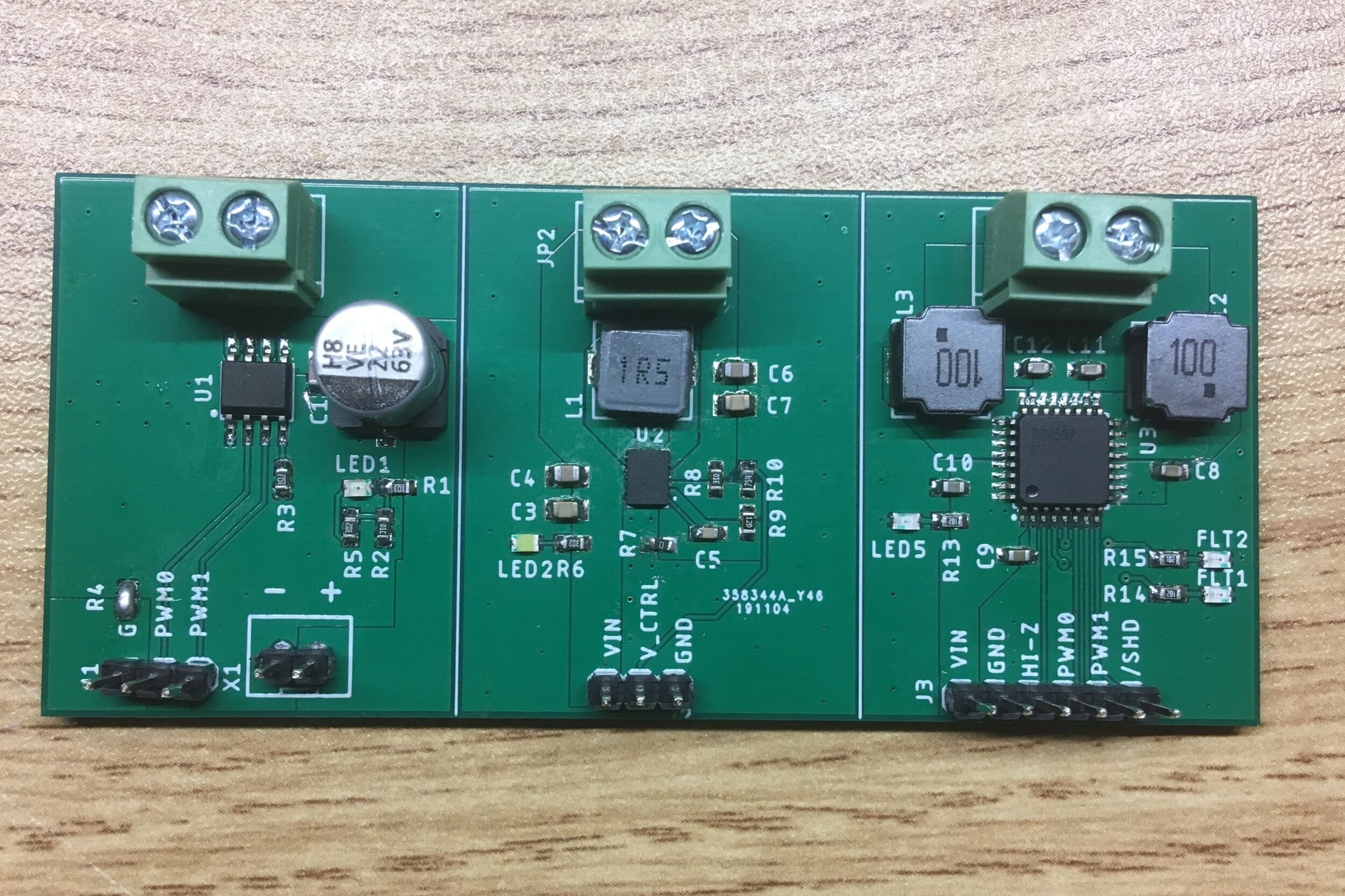
Custom PCB designed to test the three different driving methods:
DC motor driver on the left, switching regulator in the middle, H bridge driver on the right
Step 3: PCB and firmware
PCB
The thermal cycling controller is one of several modules in the PCR machine. It communicates with a master FPGA via an RS-422 interface. To maintain very low costs in this distributed control system architecture, all slave modules were based on a USD 0.50 STM32F030F4 microcontroller.
Firmware
Getting temperature from the NTC thermistors: I used a python script to generate a lookup table for temperatures, because floating point math wasn’t an option.
Piping ADC readings into DMA
PID loop running on a timer and using only integer maths
Didn’t implement RS-422 because the team hadn’t defined the protocol they wanted to use.
Two samples of the PCB